Digital Design with Verilog HDL
Introduction
Before we go into the design language, we will go through some terms and info about the concept of digital design.Digital system is any system that uses discrete values to represent and process its data, where the output can be in any form of information.
The architecture of any digital system has what is known as “Levels of Abstraction”:
- System: The system itself.
- Module: Components of the system.
- Gates: Component of the module.
- Circuit: Component of Gates.
- Device: Component of Circuits.
The process of designing and implementing digital hardware goes into many stages:
- Design specification and description: specify the idea of the design, draw some schematics (if applicable).
- RTL (Register-Transfer Level) Description: Used with an HDL to model digital circuits in terms of hardware registers and logic operations. Simply we can say that we write HDL code in this stage.
- Verification (Simulation) and testing: Simulate the HDL code wrote before through some software like ModelSim Altera and verify its results.
- Synthesis: The process of converting HDL code into gate-level design.
- Synthesis verification.
- Physical Implementation (Typically, it’s a industry stuff
 )
)
Verilog:
- Easier to learn.
- Used more in industry designs.
- Has more high-level constructs (Packages, Configurations, … etc.)
- More type checking by the simulator.
As an analog to any programming language, Verilog has its own basics like data types, module, …. etc.
Basic Data Types:
- reg (short for register): reg is variable that can hold data, the data is still in it until assigned other value.
- wire: represents physical connection, doesn’t hold any data.
wire b; (1-bit wire of name b).
The previous data structures can hold any of the following values:
- 1: Logical High.
- 0: Logical Low.
- Z: floating or disconnected (Usually for registers)
- X: Unknown value, neither 0, nor 1, nor Z.
to define multiple registers or wires, we use the vector notation:
reg [7:0] Data; //8-bit register with Data[7] as the MSB.
reg [0:7] Data; //8-bit register with Data[7] as the LSB.
wire [3:0] V; //4-bit wire connection.
c[6:5] // gets bit 5 and 6 of vector c.
a[3+:4] // gets bits 3 to 6 of vector a.
The last two styles are rarely used.
Constants are defined in the following form (without brackets):
<size>’<base><value>
where:
size: size of the constant.
base: b/B binary, o/O octal, h/H hex, d/D decimal.
value: constant value. the _ sign could be used as a space. If value less than space, constant could be 0, X, or Z- extended (Default depends on the simulator and synthesizer software).
Examples on Constants:
6′b010_111 = 010111;
8′b0110 = 00000110;
8′b1110 = 00001110;
4′bx01 = xx01;
16′H3AB = 0000001110101011;
24 = 0….0011000; // defaulted as decimal, size depends as the extension does.
5′O36 = 11100;
16′Hx = xxxxxxxxxxxxxxxx;
8h’z = zzzzzzzzzzzzzzzz;
The module is the basic unit of design as we stated before. The general form of the module is the following:
module name(portlist); // portlist: you write all the port names here.
port declarations; // specify input, output, inout ports and sizes of each.
parameter declarations; // same as const x in C/C++.
wire declaration; // here you define
reg declaration; // wires and registers as needed.
module instantiations; // create a copy of other defined modules, same as function calls in C/C++.
always blocks;
initial blocks;
functions and tasks; // all of these will be discussed later.
endmodule
Keywords so far: reg, wire, module/endmodule.
Before we go into writing and designing modules, we should consider one thing; we are designing at RTL level, which will be converted to physical hardware by compiling the Verilog code and performing synthesis, as a result not all Verilog commands and keywords are synthesizable; to be converted to physical hardware. We will go into much more detail once we get to know more keywords.
There are 3 modeling types in Verilog:
- Structural model: A model with sub-module (instantiates other modules in it) and gates.
- Procedural model: Uses always and initial block, more likely in a form of a procedure.
- Data flow model: you can think of it as controlling the data using the assign statement.
The D-Flip flop (D-FF) is a sequential circuit that takes the input and put it on the output in the next clock cycle (1-bit shifter). Two types: Synchronous (the operation depends only on the clock signal) and Asynchronous (depends on both the clock and the reset signals).

See how the ports were declared as input or output. The always block will be discussed in much more details, but think of it as an infinite loop, executed whenever the input between () are changed. (What about the design? Sync or Async?)
The output was defined as reg; you can think of this as the output of the module hardware is connected to a register, just for testing the values of the output.
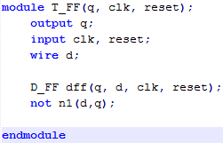
Example #2: T Flip-Flop
The T-FF is a D-FF with inverted feedback; instead of q gets the value of D, it gets ~D.

Notice that to instantiate other modules, in some cases you must put a name to the instance of that module. The output of that instance must be a wire, and to test some values for the input, it must be defined as reg then passed to the instance. We will talk more about that in simulation part.
You see that we have used the initial block but we didn’t talk about it, this block is VERY essential in designing sequential circuit.
Example #3: Half and Full Adder

The instantiation of logic gates is simple, just the name of the gate, a name for the instance and between brackets put the output first then the input.
Just for exercise, try to write the model for a 4×1 Mux and a 4-bit comparator.


It looks so natural, however the outcomes are shocking! I can hardly wait to attempt this by the enormous window by our stairs! A debt of gratitude is in order for this!Clipping pathThanks For You Sharing.
ReplyDelete